
Introduction#
It’s time to move to the next level of components. In this post, we’ll be building more complex but manageable components: multiplexers (MUX) and adders.
Multiplexer (MUX)#
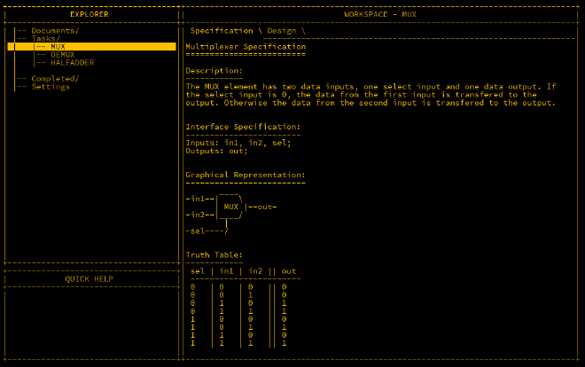
A multiplexer (MUX) is an essential component that takes two inputs and, depending on a third input called sel (selector), outputs the value of either in1 or in2. If sel
is 0, in1 is outputted; if sel is 1, in2 is outputted.
Here’s a diagram of the MUX:
Let’s break it down further: when sel is 1, the output is true if both sel and in2 are true, which is achieved using an AND gate.

For in1, as sel is false, it must be inverted via a NOT gate. The outputs of the two AND gates are then fed into an OR gate.

The MHRD code for wiring the MUX looks like this:
Inputs: in1, in2, sel;
Outputs: out;

Parts:
 n NOT,
 a1 AND,
 a2 AND,
 o OR;

Wires:
 in1 -> a1.in1,
 in2 -> a2.in1,
 sel -> n.in,
 sel -> a2.in2,
 n.out -> a1.in2,
 a1.out -> o.in1,
 a2.out -> o.in2,
 o.out -> out;
Demultiplexer (DEMUX)#
A demultiplexer (DEMUX) performs the opposite function of a MUX: it takes one input and routes it to one of two outputs, based on the value of the selector input.
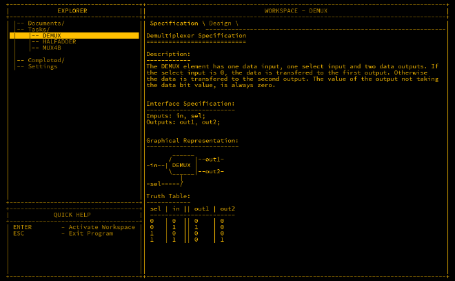
Here’s a logical arrangement of the DEMUX:

The truth table shows that each output is activated by different selector conditions. Two AND gates and a NOT gate are used to route the input based on the selector value.

The wiring for the DEMUX is as follows:
Inputs: in, sel;
Outputs: out1, out2;

Parts:
 n NOT,
 a1 AND,
 a2 AND;

Wires:
 in -> a1.in1,
 in -> a2.in1,
 sel -> n.in,
 n.out -> a1.in2,
 sel -> a2.in2,
 a1.out -> out1,
 a2.out -> out2;
MUX4B#
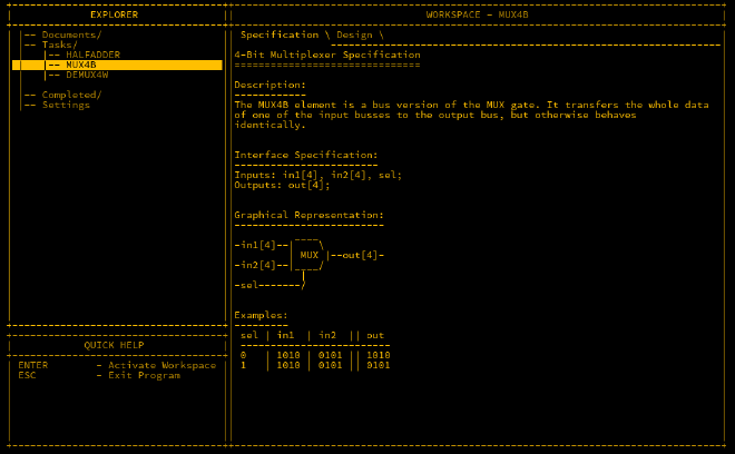
The MUX4B is an extension of the standard MUX to handle a 4-bit bus. It takes two 4-bit inputs and a single selector.
The wiring for the MUX4B looks like this:
Inputs: in1[4], in2[4], sel;
Outputs: out[4];

Parts:
 m1 MUX,
 m2 MUX,
 m3 MUX,
 m4 MUX;

Wires:
 in1[1] -> m1.in1,
 in1[2] -> m2.in1,
 in1[3] -> m3.in1,
 in1[4] -> m4.in1,
 in2[1] -> m1.in2,
 in2[2] -> m2.in2,
 in2[3] -> m3.in2,
 in2[4] -> m4.in2,
 sel -> m1.sel,
 sel -> m2.sel,
 sel -> m3.sel,
 sel -> m4.sel,
 m1.out -> out[1],
 m2.out -> out[2],
 m3.out -> out[3],
 m4.out -> out[4];
DEMUX4W#
As the name suggests, DEMUX4W is a demultiplexer with four outputs. This requires a 2-bit selector since four outputs cannot be selected with only one bit.
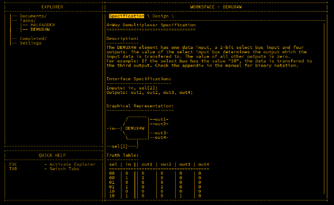
The first bit in the selector decides whether the output is routed to out1/out3 or out2/out4. The second bit further narrows it down to one of the four outputs.
The wiring is:
Inputs: in, sel[2];
Outputs: out1, out2, out3, out4;

Parts:
 d1 DEMUX,
 d2 DEMUX,
 d3 DEMUX;

Wires:
 in -> d1.in,
 sel[2] -> d1.sel,
 d1.out1 -> d2.in,
 d1.out2 -> d3.in,
 d2.out1 -> out1,
 d2.out2 -> out2,
 d3.out1 -> out3,
 d3.out2 -> out4,
 sel[1] -> d2.sel,
 sel[1] -> d3.sel;
Completing this will unlock further components such as MUX4W16B, MUX16B, and DFF, which we will discuss later.
Half Adder#
A half adder is the foundational component of a CPU that enables basic addition. It takes two inputs and adds them. If both are 0, the output is 0. If one is 1, the output
is 1. If both are 1, the output is 0 but the carry output is set to 1.
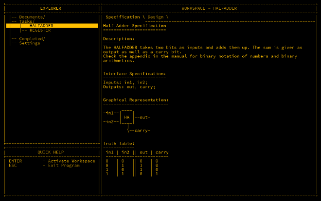
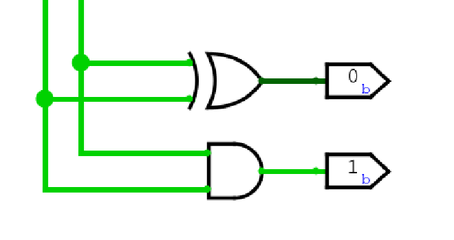
The half adder uses an XOR gate for the output and an AND gate for the carry.
Here’s the wiring:
Inputs: in1, in2;
Outputs: out, carry;

Parts:
 x XOR,
 a AND;

Wires:
 in1 -> x.in1,
 in2 -> x.in2,
 in1 -> a.in1,
 in2 -> a.in2,
 x.out -> out,
 a.out -> carry;
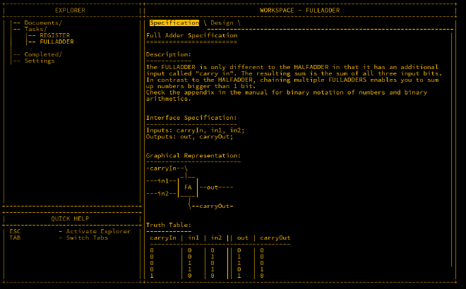
Full Adder#
A full adder extends the half adder by adding an additional input called carryIn, which is used to add bits from previous additions. This is crucial for adding larger numbers.
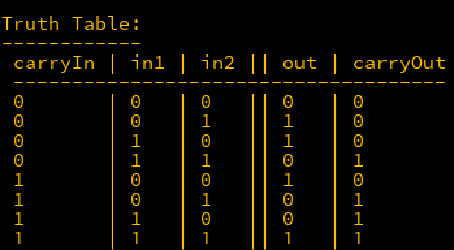
Here’s the truth table for the full adder:
The wiring for the full adder looks like this:
Inputs: carryIn, in1, in2;
Outputs: out, carryOut;

Parts:
 x XOR,
 a AND,
 o OR,
 n NOT,
 m1 MUX,
 m2 MUX;

Wires:
 in1 -> x.in1,
 in1 -> o.in1,
 in1 -> a.in1,
 in2 -> x.in2,
 in2 -> o.in2,
 in2 -> a.in2,
 x.out -> n.in,
 x.out -> m1.in1,
 n.out -> m1.in2,
 carryIn -> m1.sel,
 m1.out -> out,
 a.out -> m2.in1,
 o.out -> m2.in2,
 carryIn -> m2.sel,
 m2.out -> carryOut;
Adder4B#
Finally, we can chain multiple full adders to add two 4-bit numbers together.
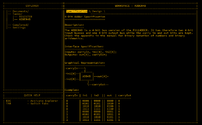
The wiring for the 4-bit adder is:
Inputs: in1[4], in2[4], carryIn;
Outputs: out[4], carryOut;

Parts:
 f1 FULLADDER,
 f2 FULLADDER,
 f3 FULLADDER,
 f4 FULLADDER;

Wires:
 in1[1] -> f1.in1,
 in2[1] -> f1.in2,
 in1[2] -> f2.in1,
 in2[2] -> f2.in2,
 in1[3] -> f3.in1,
 in2[3] -> f3.in2,
 in1[4] -> f4.in1,
 in2[4] -> f4.in2,

 f1.out -> out[1],
 f2.out -> out[2],
 f3.out -> out[3],
 f4.out -> out[4],

 carryIn -> f1.carryIn,
 f1.carryOut -> f2.carryIn,
 f2.carryOut -> f3.carryIn,
 f3.carryOut -> f4.carryIn,
 f4.carryOut -> carryOut;
Conclusion#
We have now built multiplexers, demultiplexers, half adders, and full adders. These components allow us to perform logical operations and arithmetic on multiple bits, a crucial step in constructing more complex systems, such as an Arithmetic Logic Unit (ALU).