
Introduction#
With the core concepts of the ALU now established, the next step involves wiring the device. There are various ways to tackle this, but I believe the following method strikes a good balance between simplicity and performance.
ALU4B - Wiring#
Let’s begin with the predefined inputs and outputs, along with the necessary components for the ALU:
Inputs: in1[4], in2[4], opCode[4];
Outputs: out[4], negative, zero;

Parts:
  m1 MUX4B,
  m2 MUX4B,
  m3 MUX4B,
  m4 MUX4B,
  n1 NOT4B,
  n2 NOT4B,
  n3 NOT4B,
  a ADDER4B,
  nand NAND4B,
  n NOT,
  o OR4W;
Step 1: opCode[4] - Negating in1#
If opCode[4] is true, the value of in1 will be bitwise negated. To achieve this, feed in1 into a NOT4B gate (n1). The original in1 value and the negated output from n1 are then routed into the inputs of a MUX4B gate (m1). The opCode[4] value is used as the selector (sel) to determine whether in1 is passed through unchanged or negated.
in1 -> m1.in1,
in1 -> n1.in,
n1.out -> m1.in2,
opCode[4] -> m1.sel;
Step 2: opCode[3] - Negating in2#
This step is identical to Step 1 but for in2. Here, we route in2 through a NOT4B gate (n2) and use another MUX4B (m2) to either negate or pass through the value based on the state of opCode[3].
in2 -> m2.in1,
in2 -> n2.in,
n2.out -> m2.in2,
opCode[3] -> m2.sel;
Step 3: opCode[2] - Selecting Between ADD and NAND#
If opCode[2] is 0, the outputs of m1 and m2 are passed into an ADDER4B gate (a). If opCode[2] is 1, the outputs are passed into a NAND4B gate (nand). Instead of wiring inputs to both the adder and NAND gates, we use a MUX4B (m3) to select the output of the correct operation.
m1.out -> a.in1,
m1.out -> nand.in1,
m2.out -> a.in2,
m2.out -> nand.in2,
a.out -> m3.in1,
nand.out -> m3.in2,
opCode[2] -> m3.sel;
Step 4: opCode[1] - Negating the Output#
To potentially negate the final output, route m3.out into a NOT4B gate (n3). A fourth MUX4B (m4) selects whether the output remains unchanged or is negated, based on the value of opCode[1]. The output from m4 is then sent to out[4].
m3.out -> m4.in1,
m3.out -> n3.in,
n3.out -> m4.in2,
opCode[1] -> m4.sel,
m4.out -> out;
Negative Flag#
The negative flag indicates when the result is negative. As discussed previously, a number is considered negative when the most significant bit (MSB) is 1. To implement this, route the MSB of m4.out to the negative output.
m4.out[4] -> negative;
Zero Flag#
The zero flag is used to check if the result is 0. This can be done by piping the output of m4 into an OR4W gate (o). If any bit in the result is non-zero, the output cannot be zero. Since we need the inverse of this, the output of the OR4W gate is negated using a simple NOT gate (n).
m4.out -> o.in,
o.out -> n.in,
n.out -> zero;
This wiring successfully completes the ALU, and with this component built, the 16-bit version (ALU16B) is unlocked, which performs the same operations on 16-bit inputs and outputs.
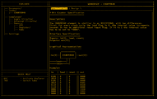
COUNTER4B#
The next important component is the COUNTER4B, which is useful for tracking the execution state of a program. The counter increments by 1 per cycle when the load flag is 0. When load is 1, the counter is set to the input value. It is reset to 0 when the reset flag is active.
The counter is essentially a REGISTER4B that loops back its output to an ADDER4B, where the carryIn is always 1, so the value increments each cycle. Two MUX4B components are then used: the first handles the load input, and the second handles the reset input. The wiring looks like this:
Inputs: in[4], load, reset;
Outputs: out[4];

Parts:
  r REGISTER4B,
  a ADDER4B,
  m1 MUX4B,
  m2 MUX4B;

Wires:
  r.out -> a.in1,
  r.out -> out,
  1 -> a.carryIn,
  1 -> r.load,
  a.out -> m1.in1,
  in -> m1.in2,
  load -> m1.sel,
  m1.out -> m2.in1,
  reset -> m2.sel,
  m2.out -> r.in;
This completes the COUNTER4B and unlocks the COUNTER16B, which functions similarly but with 16-bit inputs and outputs.
Conclusion#
With the ALU now fully operational and the counter implemented, the foundational components for the CPU are complete. The next phase will involve integrating these components to build the final stages of the MHRD CPU.